Rotation. Motors rotate. Potentiometers and variable capacitors often rotate. It is a common task to have to rotate something remotely or measure the rotation of something. If I asked you today to rotate a volume control remotely, for example, you might offer up an open loop stepper motor or an RC-style servo. If you wanted to measure a rotation, you’d likely use some sort of optical or mechanical encoder. However, there’s a much older way to do those same tasks and one that still sees use in some equipment: a synchro.
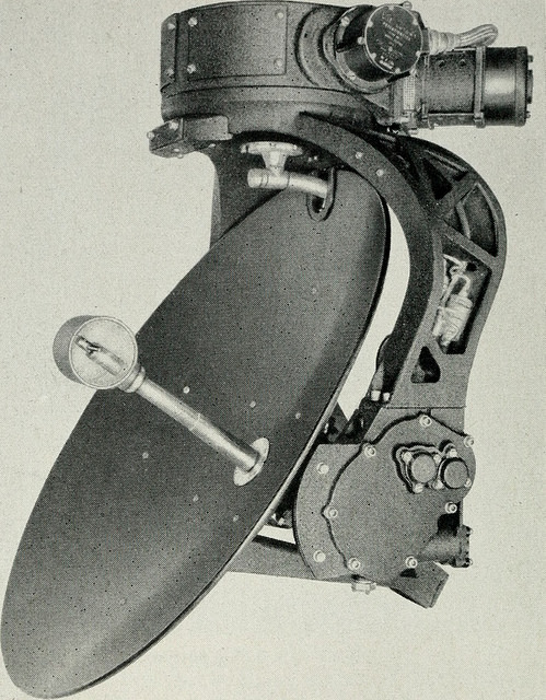
The synchro dates back to the early 1900s when the Panama Canal used them to read and control valves and gates. These devices were very common in World War II equipment, too. In particular, they were often part of the mechanisms that set and read gun azimuth and elevation or — like the picture to the left — a position indication of a radar antenna. Even movie cameras used these devices for many years. Today, with more options, you don’t see them as much except in applications where their simplicity and ruggedness is necessary.
A synchro looks like a motor, but it is really a transformer optimized for specific applications. For example, it is common to see a synchro transmitter and a synchro receiver, although usually the devices can work as both. When wired together and excited with the proper AC voltage, turning one synchro shaft will turn the other the same amount. And one transmitter can drive multiple receivers. For example, an airplane cockpit may have an instrument that uses one transmitter and has two receivers, one for the pilot and another for the copilot.
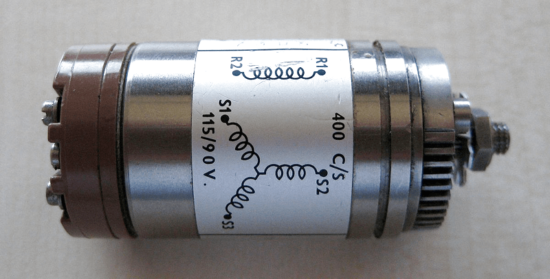
A basic synchro is similar to a motor in that it has a rotor and a stator. However, each of these has a transformer winding. Some devices use single phase and others use three-phase. In addition, devices made for vehicles probably use 400 Hz AC instead of the 50 or 60 Hz common for stationary units. Usually, light-duty units made to drive indicators use single phase but synchros that transmit torque will use three-phase connections.
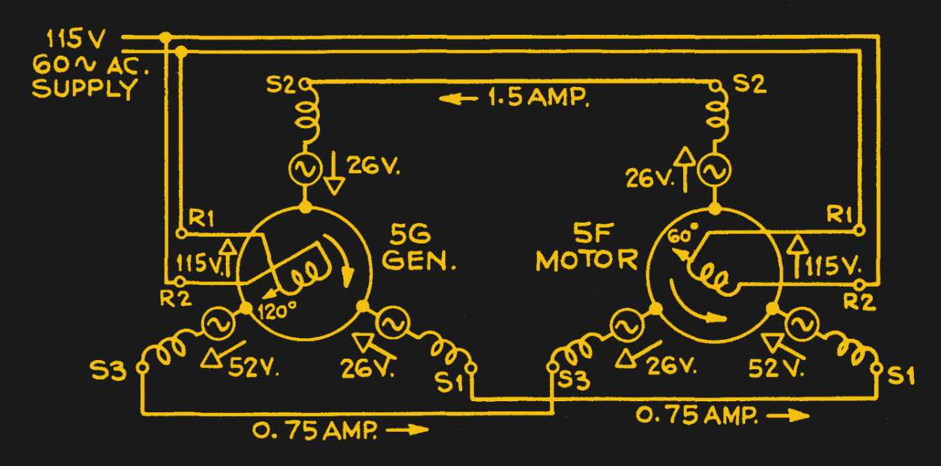
You can consider a synchro as a variable-coupling transformer. Rotating the shaft varies the magnitude of the magnetic coupling between the primary and secondary. That means the output voltage varies based on the shaft position. If you wire two synchros together, the circuit acts like a bridge. When the two devices are in the same position, the system is in balance — that is, putting out equal and opposing voltages. But if one shaft moves, the imbalance causes current to flow through the windings moving the other shaft to equilibrium. This configuration is sometimes known by the old General Electric name Selsyn. Other trade names included Teletorque and Autosyn, but you don’t hear those as often.
There are many variations. Some synchros have brushes and others are brushless. Some are made for precision. In high precision applications, you may have a coarse transmitter slaved to a fine transmitter that rotates multiple times for each full rotation of the coarse shaft for reading a more precise value. You can think of this like a clock, where the big hand goes around twelve times for each rotation of the little hand. Usually, the gearing ratio is 36:1 or 72:1 so that each rotation of the fine shaft corresponds to five or ten degrees of the coarse transmitter.
Making a little handle turn a giant gun mount was problematic. At first, the receiver motor just told a human what to do using an indicator and then the human operated the gun. However, the development of the amplidyne made it possible to amplify the synchro outputs to directly drive larger loads.
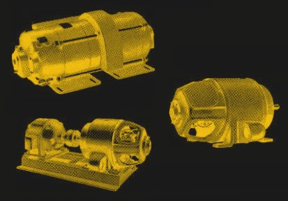
The amplidyne has a superficial resemblance to a dynamotor — that is, a generator turned by a motor. However, in a dynamotor, you turn the generator to make a high voltage. In an amplidyne, the motor still turns the generator, but an input voltage is put on the generator’s field winding. The more current you apply, the higher the output voltage. This creates a very low-frequency amplifier that takes a current input and produces a voltage output.
Amplidynes found use in other applications, too. Elevators, locomotives, and even nuclear submarines. Of course, today, we have much better options for doing high power amplification, but there could be a few still hiding in some old building’s elevator, somewhere.
Because these were used extensively in the Navy, one of the best sources of information is an old Navy pamphlet (if you consider 166 pages a pamphlet; if it disappears, search for OP 1303). If you want something more modern, Moog (the aerospace company, not the synthesizer company, although the companies were founded by cousins) has an application guide and a handbook you might find interesting.
You won’t find too many of these interesting devices in use today, although there are companies that make modern encoders that specifically target traditional synchro applications. Of course, tubes made a comeback. Maybe that pile of World War II surplus synchros in the secret Hackaday bunker will be worth something one day.
Speaking of World War II, check out the 1944 instructional video below about airplanes that could move guns electrically using all these components.
Synchro by MGeek CC BY-SA-3.0


